
Naval architects require capabilities for effective and credible hydrodynamic and propulsion system simulation. As we look to high- order tools such as CFD for solutions, we frequently encounter settings where CFD a) is too costly in time, resources, or expense for the available schedule for the nature of the problem being investigated, or more significantly, b) is not able to fully simulate the “Vessel-Propulsor-Drive” system (for prediction of fuel consumption or emissions, for example.
It is precisely these scenarios where a system simulation executive (such as HydroComp NavCad) can be paired with CFD calculations and employ multi-order modelling to improve workflow efficiency, reduce expense, and provide answers in a whole-system perspective. Let’s first consider the possible computational solutions that we have in our hydrodynamics and propulsion system analysis toolbox: high-order models, simplified physics models, and statistical models.
You’ll note that we are calling these “models”. It is important to appreciate that none of these are reality, they are different models of a particular reality. Each has its place in ship design depending on the kind of problem that needs to be solved, the resource-to-value budget, and competency in the use of the model.
High-order CFD models determine pressures and velocities for a body moving through a fluid in a defined space. Bodies can be hulls, appendages, propellers, and other components of a system – and meaningful design metrics, such as drag, lift thrust, torque, are found by integration of the various pressures. Special characteristics, such as vorticity or cavitation (either its incidence or its fully formed volumes), can also be derived and observed. A multi-component analysis in the CFD space is limited to its “wetted” components – such as the self-propulsion analysis with hull, stern gear, and propeller.
Everything is a system problem first and a component problem second
Step back for a moment and consider “what is a shipowner buying?” You might say engineering services. Well sure, but at the end of the day, what is a shipowner buying?
Speed and thrust. They are buying speed and thrust. Speed is the difference between a ship and a buoy. It is what fulfills a business plan for a merchant shipping company. It allows a motor yacht to visit different locales. It lets a race team take the checked red flag. Thrust is the critical “product” delivered by tugs. Thrust pulls fishing nets, or the anchors for oil rigs. It allows a ship to make speed.
But there is more. Every business is run on the ratio of benefit-to-cost. High-order CFD analysis can indeed give us figures that reflect the benefits of speed and thrust and to a certain extent the cost of propulsion torque (with a self-propulsion analysis). However, unless all components of the “Vessel-Propulsor-Drive” system are evaluated, we are missing several critical pieces of the cost equation. Fuel consumption is perhaps the most obvious and significant operational cost, but there are anallary costs to be considered – the environmental cost of emissions or the social cost of radiated noise. Then we need to look at capital costs. Is the engine power – and its power curve across the anticipated rpm range – sufficient to handle the expected thrust margins that might be encountered? There is also the cost of getting a component wrong. Is the shaft rpm giving us the best propeller efficiency, or will performance be compromised because we made a poor early decision?
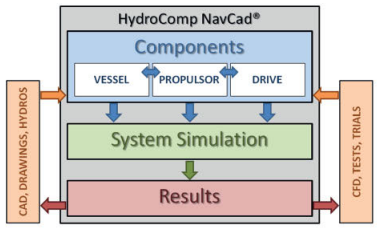
Figure 1. Application of reduced-order tools for system analysis.
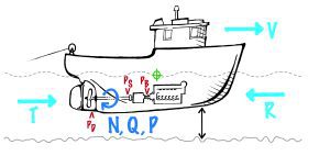
Figure 1 describes the principal components of the system, and the interconnected equilibrium shared by the Vessel, Propulsor, and Drive.
As noted, one of the challenges of CFD for ship design is that it cannot easily provide a simulation framework for the system. It is an indispensable contributor for analysis and design of the Vessel and Propulsor components of the system, and for their interaction, but the connection to the Drive and its corresponding “cost” metrics of fuel consumption, emissions, and noise are not easily modelled.
This is where a system-focused tool, such as HydroComp NavCad, can be coupled with CFD to provide an optimised workflow for complete system analysis. NavCad’s simplified physics and statistical models are the backbone of a reduced-order system simulation framework that can be enhanced with coupling to higher-order CFD computations when circumstances justify an increased fidelity.
Figure 2. System simulation framework of NavCad.
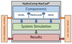
NavCad provides several coupling strategies with CFD. Figure 1 describes the system simulation framework of NavCad, its library of reduced order models for component analysis, and its potential connection to higher-order CFD – both as a receiver of CFD prediction results and as a source of information back to the CFD computation space. Interaction with CFD can be loosely or tightly coupled, depending on the communication approach and the requirements of the calculations.
So how can we make the best use of our higher-order tools? A variety of strategies are available for naval architectural offices to significantly improve CFD outcomes and workflow effectiveness, including the use of “frugal CFD” and modified actuator disk modelling.
Frugal CFD
One popular feature of NavCad is its “Aligned Prediction” capability, whereby one of the available resistance prediction models can be “aligned” to a specific reference ship. Many design are related to earlier work, so it can be valuable to leverage the knowledge invested in prior model testing and/or sea trials to help achieve the highest fidelity prediction for the new design. The Aligned Prediction feature deconstructs existing performance as defined by these tests or trials, then rebuilds, scales, and correlates the resistance prediction of the design under investigation to the reference ship. In other words, the alignment learns how a method deals with a known reference, and correlates the new prediction based on what it has learned.
This process can also be used with CFD results instead of empirical test/trial data, so that the performance of the reference ship is the CFD prediction of the subject design itself. In this case, we can obtain high fidelity outcomes with a limited number of reference ship CFD runs. For example, we may be investigating 10 or more speeds in a NavCad design session, but we generally need far fewer speeds to be run in CFD to obtain suitable figures for alignment. There is no need to spend the resources on additional intermediate runs – NavCad can handle that.
A distribution of four speeds is generally sufficient, and they are best placed at Froude numbers reflecting the nature of the ship and the operating objectives. Of course, including a run at the project’s design speed makes sense. Then add FNs that match hydrodynamically significant
speeds in the wave-making curve, such as the typical 0.30 FN hump for displacement hulls or the 0.45-0.50 FN peak of a semi-displacement fast craft. NavCad’s higher-order ADVM resistance prediction method – a feature of the Premium Edition- can provide additional guidance for the FN positions of wave-making humps and hollows.
A similar strategy can be applied to propeller alignment using NavCad’s “Aligned Series” option. This utilises the KTKQ curve of a “reference propeller” for alignment, and open-water CFD calculations at a few J values will provide sufficient distribution.
Modified actuator disk modelling
Full rotating-frame 3D CFD computation of propeller performance can be very costly in time and resources, so it is quite common to replace the propeller with a “proxy” virtual propeller – the actuator disk (AD). In many CFD tools, the AD is seeded with a KTKQ curve that is used to estimate body force sources for the disk.
The AD is a simplified physics model of the propeller. For the benefits of greatly reduced computation time and development complexity, we accept that there are going to be differences between the AD prediction and higher order 3D CFD prediction of the propeller component. For many purposes, the simplifications are acceptable. However, there are cases where the traditional AD omits important force vectors.
Figure 3. The various forces in play and the representative coefficients.
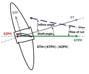
The actuator disk body forces extracted from the KTKQ data are “in-plane”, where thrust forces are axial in direction and torque moments are tangential (or circumferential in the plane of the AD). Any propeller in oblique (non-axial) flow will introduce forces perpendicular to the propeller shaft, as well as an effective reduction in the axial thrust. These missing forces and corrections can be very influential for the determination of high-speed planing craft performance. In other words, when using an AD for the propeller component, the omission of the lift-generating normal force and axial thrust correction can result in a system analysis that is fictitious.
A recent addition to NavCad is its calculation of normal force for a propeller in oblique flow, and export of this data in a special propeller KTKQ data file. This can be used within the programming scripting feature of CFD codes to provide the missing lift force vector. Figure 3 illustrates the various forces in play and the representative coefficients. This data can be prepared in advance with a specified propeller or delivered in real-time for case-by-case propeller matching via dynamic server mode coupling with NavCad Premium.
Finding Efficiency
Whether we are referring to propulsion system efficiency or design workflow efficiency, the pairing of multi-order tools can provide substantial benefits to the engineers and naval architects responsible for delivering a successful ship to an owner. Get the system simulation functioning first. Then use the tremendous benefit available to you in your higher-order CFD assets as effectively as possible to improve the components of the system.
Download this article here.