

*This article was originally published in the October 2023 issue of The Royal Institution of Naval Architects’ The Naval Architect, written by HydroComp Technical Director Donald MacPherson.
The increased use of CFD for hydrodynamic analysis over the last decade has been remarkable, with tools becoming more commercially attainable and accessible. Designers are now looking to CFD for confirmation, optimisation, and better understanding of the hydrodynamic aspects of their designs. While CFD is now expanding insights to a larger audience, practitioners must also develop the means to judge when CFD computations are being appropriately modelled and conducted.
These judgements of computational fidelity often come from reference validations, both from in-house experience and public data. That said, validation studies are of a specific application that may, or may not, be relevant to the project at hand. To generate suitable references for CFD quality assessment, we call on other tools to provide qualitatively and quantitatively strong validation predictions quickly and efficiently. HydroComp’s NavCad and PropElements software are two of the most widely used tools for Vessel-Propulsor-Drive system simulation and propeller detail design.
To understand how NavCad and PropElements fit into the hydrodynamic design workflow with CFD, let’s break down a typical design process. Everything is a system problem first. Component design is not worthwhile until the system functions well together. NavCad provides various parametric and distributed volume models for vessel resistance and hull-propulsor factors, propulsor thrust and torque, and drive power delivery. NavCad’s effectiveness for early-stage design is evident, narrowing the design space for future CFD confirmation and review but it can also provide substantial assistance to CFD analysis for initial propeller modelling and to generate benchmark results for confidence in the CFD results.
NavCad oblique-flow propeller models for actuator disks
One of the realities of CFD computations is that they take a long time, and we use certain simplifications where they are appropriate and valid. The use of a virtual proxy propeller model – the actuator disk (AD)is one such ADs are typically fed with propeller open-water J-KT-KQ data (and often also with wake fraction) to provide the thrust and torque figures that generate momentum body forces in a propeller disk area. However, when a propeller is placed in “oblique flow” with a shaft angle, the open-water KT-KQ figures are no longer valid. NavCad can consider the effects of non-axial flow, including a corrected KT* for ADs that accounts for a KT oblique flow vector loss and the often overlooked in-plane vertical normal force (shown as KZP). These both can be significant omissions, particularly for planing craft where thrust line and stern lift forces are important contributors to a proper equilibrium force and moment model.

Controlling torque-limited computations
Not all computations are for steady-state design conditions. In cases of dynamic operation and loading – such as vessel acceleration or manoeuvring – sometimes we need to understand and control CFD analyses to the limits of drive system operation. NavCad provides a system-level simulation model that can generate drive-specific speed- rpm-power limit data for functions to apply as a control to CFD self-propulsion computations, whether the drive be a diesel engine or electric motor. This can even be extended to dynamic oblique conditions for refinement of results at different dynamic trim angles, for example.
Closely coupling NavCad for interactive dynamic data
Both examples above generate important static data that can be sources for development of “look-up” functions. In some cases, such as controllable-pitch propellers (CPPs), a multi-dimensional static reference can be cumbersome. In these circumstances, the server mode feature of NavCad Premium can be used to dynamically provide performance data back to CFD in real-time. When closely coupled to a CFD code using the server mode feature, NavCad becomes the source for dynamic generation of KT-KQ data, or even specific rpm, thrust, and torque figures.
The benefits of closely coupling NavCad Premium as a calculation server go both ways. In addition to providing dynamic propulsor data to CFD, NavCad can also exploit the vessel resistance data coming from CFD as the reference for system modelling. This establishes NavCad as the executive responsible for the system simulation, with the CFD code accepting updates for the appropriate propeller performance and hull-propulsor coefficients at the indicated time-step condition, then delivering back to NavCad updated resistance (and trim, as indicated) – even incorporating CFD-generated figures for appendage and windage drag.
Full wake-field modelling via closely coupling PropElements with CFD
A full self-propulsion CFD computation with rotating- frame/sliding-mesh propeller models can provide a lot of insight but is typically too computationally rigorous and time-consuming to be effective in design. (Remember, design is largely about iterative analysis, with each generation improving on the former until a conclusive iteration is reached.) While the AD is a suitable proxy stand-in for a propeller in early-stage design or where precision of local forces or velocities are not required, there are many cases where a more realistic model of a propeller is needed – but one without the computational overhead. (Appendage flow alignment, such as twisted rudder design, quickly comes to mind.)
To achieve this, PropElements can be used as a replacement for the AD, reaching nearly the high fidelity of a full 3D propeller computation with the low cost in resources and time comparable to the AD. By dynamically coupling PropElements in server mode, a proper radial and circumferential distribution of body forces can be developed in PropElements and transmitted to CFD. Velocities around the propeller disk (taken either as a pre-propeller or post-propeller wake disk) are transmitted to PropElements for extraction of effective wake velocities (via its internal calculation of induced velocities) and jet compression around the disk area. Body forces on the propeller disk are calculated and returned to CFD for use as momentum sources.
PropElements preparation of geometric models for CFD
Everything we think we understand about a ship’s propeller is generated by a model. While models can have different levels of precision, all share two principal sub- models – a geometry model and a computational model, and it is important to get both right. In the case of propellers, the geometric model is frequently generated from pre-defined curves and profiles. However, arbitrary development of a 3D propeller simply as a proxy for CFD analysis does not take advantage of a propeller geometry that has been designed to meet the performance objectives – not only objectives of high efficiency, but also with considerations of cavitation, hydroacoustics, tip unloading, even blade strength. PropElements provides the “design for performance” platform for the appropriate wake-adapted propeller design first, and then for generation of full 3D geometry for CFD in surface and mesh formats.
Not only can propeller blade geometry be exported in 3D IGES or STL formats, but additional pieces of the CFD geometric space can be generated. Notably, users can develop volumes for the near- and far-field domain, as well as the rotating and fixed volumes. For cases with nozzles, a collection of popular nozzle styles can also be quickly exported as 3D models at the appropriate size to match the propeller and tip gap requirements.
Confident benchmarks for quality assurance
The complexity of geometric and computational models can lead to uncertainty, particularly for those new to the use of CFD for hydrodynamic analysis. Variation in geometric models come from different strategies in meshing and refinement, as well as near- and far-field domain sizing. Very localised shape characteristics can alter decisions in turbulence modelling and time-steps. For example, different characteristics of trailing-edge curvature on a propeller blade can greatly affect decisions on the time steps for advancing the blade. Remember, geometric and computational models must reflect the physics of the shape characteristics. If you are trying to investigate the development of a shed vortex stream, you must advance the body in very small steps. If your objective is basic force development, then larger steps may be acceptable.
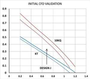
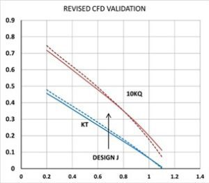
FIGURE 2
For example, PropElements saved one CFD user from substantial embarrassment by providing a benchmark that clearly indicated something was amiss with the CFD calculation. In the KT-KQ plot in Figure 2, you can see the CFD results (solid) and the PropElements calculation for the same propeller (dashed). (Of course, the first task in this validation study had been to confirm the PropElements calculation with a validation of its own against test data of a propeller with very similar style and parameters.)
As you can see, for the initial CFD study there is substantial difference in KT and especially KQ between the PropElements and CFD open-water calculations. The team discussed the potential cause of the difference, including grid count, edge condition (particularly the trailing edge curvature), and the CFD viscous and turbulence settings. The actual cause of the problem was soon found to be much more fundamental (and obvious, as can be seen in Figure 3). The propeller geometry was pushed to meshing as a faceted surface. The blade sections used sparse offsets, were left as polylines, and not splined into smooth curves before lofting the surface. No visual check was made on the geometry, due to a push to automate the process. The PropElements benchmark caught the issue, the geometry was corrected, and a revised CFD computation was completed – with much greater confidence going forward.
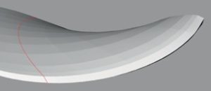
FIGURE 3
CFD practitioners benefit from pre-defined expectations on the magnitudes of the attributes being investigated. Resistance computations can employ NavCad’s bare- hull and added drag predictions and comparison to its “confidence plots” for benchmark validation. PropElements gives you similar benchmarking benefits with details on a whole-propeller level (such as thrust and torque, or KT-KQ plots) and on a distributed level (including induced and total velocities), all of which can be used to validate the CFD computation.
You have invested a lot in CFD. Companion tools like NavCad and PropElements offer useful and important guardrails to help you achieve the best outcomes and return on that investment. ■
Download this interview here.