
This article has been reprinted with permission from the October/November 2020 issue of Marine Propulsion & Auxiliary Machinery.
Successful vessel performance outcomes don’t happen by accident. They start with the analysis of a complete Vessel-Propulsor-Drive system model, and specifically one that that faithfully reflects the “in-the-water” function of the system’s components. And given that the Propulsor is the central element that connects the potential of the Drive with the demand of the Vessel, properly modeling a propeller is critical to a proper understanding of overall system performance, determining efficiency and engine load, analyzing cavitation and blade area requirements, as well as predicting the environmental impacts of fuel consumption, GreenHouse Gas emissions, and even underwater noise.
While propeller performance can be predicted using many different approaches, for system-level studies the “heavy lifting” is still conducted with parametric propeller performance calculations such as those found in NavCad. These are often referred to as 1D calculations, reflecting their use of individual “whole propeller” parameters, such as a parent blade style, diameter, pitch, blade area, and blade count. (Higher order calculations that take into account local shape characteristics include 2D wake-adapted calculations such as PropElements, as well as 3D RANSE CFD calculations or other specialist propeller codes.) Parametric methods are based on the dimensional analysis of the thrust and torque coefficients (KT-KQ) from model tests, and are collected, of course, into what we call propeller “series”.
Each series has a single common parent blade style, with ducted propellers also having a shared nozzle style. There are many published series, but a few of the more popular are B Series, Gawn AEW/KCA, AU/MAU, and the Kaplan Ka/Kc ducted propeller series. Most published series were actually developed decades ago, which presents the conundrum – how can we use these series to faithfully model today’s contemporary propellers?
There are a number of strategies that can be applied to ensure that the relationships between speed, RPM, thrust, and power are properly represented in the Vessel-Propulsor-Drive system analysis. So let’s first discuss how contemporary propellers differ from traditional propeller series, and we will use the well-known B Series for reference (Figure 1).
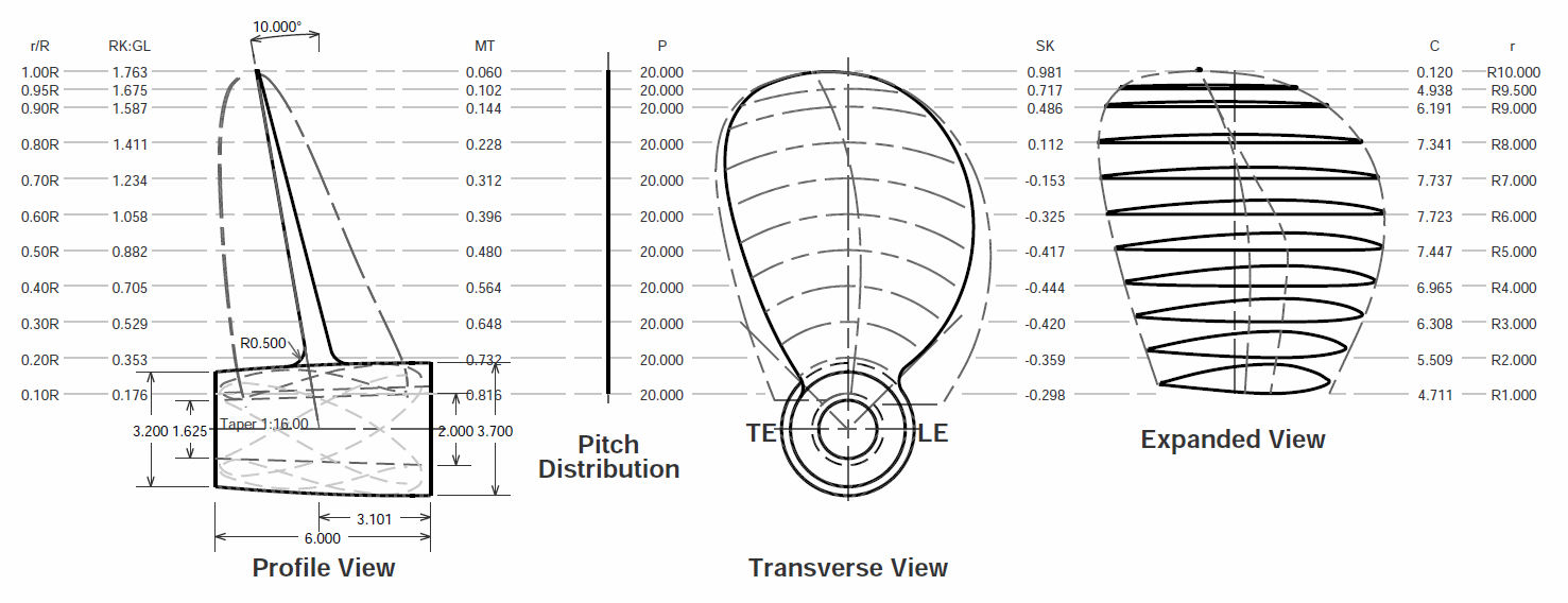 Figure 1 – B Series
Contemporary propellers depart from the traditional series in a number of ways.
- Pitch distribution. Many series were developed and tested using constant pitch. (The 4-blade B Series is an exception, with a slight reduction of pitch into the root.) Contemporary propellers are largely of variable pitch so that they are adapted into the inflow. It is therefore necessary to determine a hydrodynamically-significant mean effective pitch for the blade. This is found through a chord-radius integration of pitch. (Utilities to calculate mean pitch can be found in all of HydroComp’s propeller design and analysis tools.)
- Blade section foil shape. Contemporary propellers utilize a different foil section than traditional series. These section shapes are often designed for uniform chordwise pressure distributions so that they can carry greater thrust loading without cavitation. This change in pressure distribution also leads to differences in lift and drag characteristics, which then make the propeller’s thrust, torque, and efficiency different from series propellers. So, the series KT-KQ curves need to be modified to suit.
- Section curvature. This is an important characteristic of new propeller designs. Traditional propellers often are based on “flat-faced” designs, whereby the pressure “face” flatly sits on the defined helix. (We can see that, for example, in the outer radii of the B Series.) If thrust loading is pushed to the point of excessive cavitation, one design response can be to modify its pressure distribution by adding curvature to the trailing edge (cupping) or more broadly to the entire section (camber, illustrated in Figure 2). This also adds lift to the section (and changes drag). Added cup or camber therefore shifts the KT-KQ curve for the same pitch value, so this would also require modification to the series KT-KQ values.

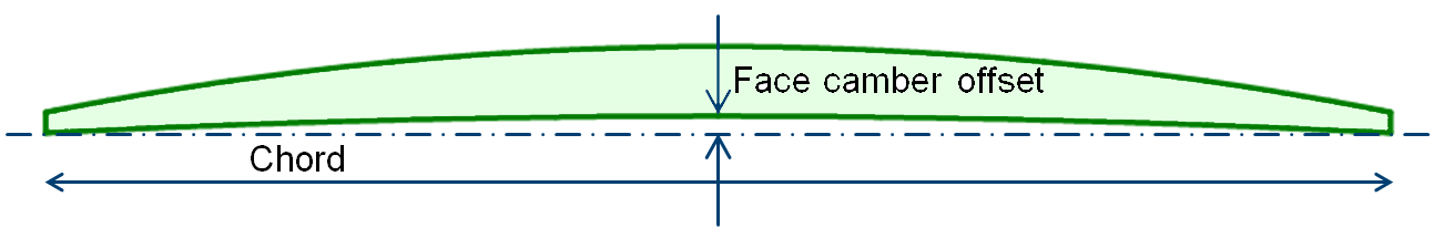
Figure 2 – Added camber
So, how do we respond to these differences between contemporary and series propellers? How can continue to use traditional series appropriately? Well, there are three principal approaches utilized in NavCad, for example, to achieve this objective – a) analytical corrections, b) rudimentary KT-KQ correction factors, and c) alignment to model test data or computations from higher order codes.
- Analytical corrections. NavCad provides explicit analytical predictions for the addition of cupping or camber to the traditional series. This is particularly useful for commercially-available motor yacht and work boat propellers that are based on the flat-faced Gawn series. Many commercial variants have added camber (also called “progressive pitch”, characterized in NavCad by an added “face camber ratio”). Analytical corrections are also available for differences in blade thickness.
- KT-KQ factors. These are just what it seems – user entered multipliers and shifts to the series KT-KQ curves. Some correction factors are universal, such as a small reduction in KT for large CPP hubs or small increase in KQ for thick edges. Other factors can be estimated from a comparison to model tests or other references, such as factors to approximate the influence of differences in blade section foil shape.
- Series alignment. NavCad’s “Aligned Series” option offers the most reliable and comprehensive way to predict the performance of contemporary propellers. That said, it does quire one source of KT-KQ data from a model test or higher-order computation. Through the use of appropriate internal non-dimensional scaling functions for speed (including the effect of induced velocities) and KT-KQ, very accurate predictions can be achieved even when the number of blades, blade area, and pitch are different. For example, the following plot (Figure 3) illustrates how KT can be very closely modeled for a 4-blade, 0.64 EAR, 1.06 P/D contemporary propeller using a 5-blade, 0.80 EAR, 0.96 P/D reference propeller.
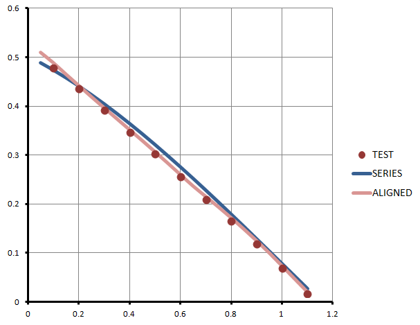
Figure 3 – Alignment example
In summary, ensuring the highest fidelity in Vessel-Propulsor-Design system analysis requires proper modeling of the propulsor. For marine propellers, traditional propeller series can be effectively used when appropriate attributes, corrections factors, or series alignment is applied.
AUTHOR BIO
Donald MacPherson is Technical Director of HydroComp, Inc., a research consultancy specializing in applied hydrodynamic and propulsion system simulation. Widely regarded as one of the industry’s foremost experts in analytical prediction methods for the performance of marine vehicles and propulsors, he oversees all software product development and is principal investigator for engineering services. A graduate of Webb Institute, Don is a Fellow of the Society of Naval Architects and Marine Engineers, and member of its Propeller Hydrodynamics and Underwater Noise panels.
Download the full article: Propellers_MPOCT20.pdf