
By Don MacPherson, HydroComp
When asked to reflect on the use of computers for propeller design over the last fifty years, my first reaction was to think about my own history with computers. I painted houses one summer in the mid-1970’s to buy a TRS-80 that I took with me to university. One of my first programs at school was to code the B Series KT-KQ polynomials published just a few years before. That auspicious start offered me the distinct privilege of a career both as a propeller designer and as a developer of design tools. My work has always focused on the practical applied-engineering side of propeller design and computers have been an essential tool from the start.
I believe that the use of computers for any engineering design task offers but two significant potential benefits – a) to reduce the amount of time spent on a task, or b) reduce the uncertainty of the task’s output. And the two principal disciplines of propeller design fall in opposite camps.
Design for production
The use of computers for the production of propellers distinctly points to the first benefit – to reduce the amount of time spent on a task. This is possible only because the result of the task is already known. The deliverable is a representation of the propeller suitable for manufacture. We tend to think of CAD as the principal design task for production, but over the last fifty years computers have come to play a much more comprehensive role in geometric design, manufacture, and post-delivery quality assurance.
In some ways manufacturing processes and design tools evolved hand-in-hand. For example, propeller-specific CAD evolved from home-grown spreadsheets producing drawings for manual layup of patterns to commercial tools providing outputs for 3D manufacturing technologies. Design drawings and offset tables may seem old-fashioned, but they are still a very important CAD task for documentation and regulatory compliance (such as for class societies). Of course, many production processes are now direct-to-3D so the computer tools must replace manual lofting and pattern-making skills with “expert system” guidance.
The introduction of CNC milling for propellers also introduced challenges for 3D geometric design. When the shapes depicted by drawings and offsets could be manually modified or altered during lofting, a certain amount of tolerance in the representation of the propeller geometry could be accepted. That is not the case with a direct-to-3D representation, since this is the exact shape to be manufactured. Algorithms used for 3D surface modeling often encountered issues at the propeller tip, as the numerically lofted surface converged on a singularity. This required new computer design options for blade stacking and curvature control to create “CAD-friendly” blade tips.
Post-delivery inspection for quality assurance or repair has also evolved from manual to computer-based processes over the last fifty years. With the advent of personal computers, traditional polar-coordinate drop-rod devices were instrumented with digital pickups for use with inspection software. Unfortunately, criteria for acceptable tolerance has not likewise evolved, so the newly connected inspection tools were (and still are) subject to traditional manual-process tolerance criteria. Even so, the reduction in time spent on inspection was substantial, leading to significant benefits in process efficiency and cost reduction. New devices and software are also being integrated with repair equipment, leading to even more benefit in cost, time, and even technician safety.
Recent advances in 3D scanning technology has made possible the development of in-situ propeller inspection. While this is currently applied as a “virtual” device that mimics the traditional polar drop-rod methodology, it is raising interest in development of new 3D-specific tolerance criteria. (In fact, some of our most interesting in-house “innovation studies” are about matching propeller geometric tolerance to performance outcomes.)
Design for performance
Unlike design for production, I hold no illusions that computers offer any time savings in design for performance. It seems like we take more-or-less the same amount of time now as we did fifty years ago to complete a propeller design task or hydrodynamic study. The real benefit is improved clarity, reduction of uncertainty, and the elimination of over-cautious design margins.
Short of building a propeller and testing it, design for performance is about using proxy models for how a propeller will generate thrust, absorb torque, develop cavitation and noise, and to find the appropriate design parameters that will optimize some of these and limit or avoid others. The evolution of computer hardware and propeller design software over the last fifty years has indeed been remarkable, but has not changed our overall design process all that much. Let me explain by following the typical propeller design process.
Propeller parameter selection for system design
During initial design, the objective is to determine the principal propeller parameters that will allow the Vessel-Propulsor-Drive system to best function. Parameters might include diameter, mean pitch, shaft RPM, blade area, number of blades. At this stage, we are a long way from needing the fully 3D representation of the propeller, so our proxy performance model is typically semi-empirical and based on systematic series with corrections as needed to correlate the series to expected in-the-water performance.
Those of my generation will remember the various propeller series “design charts”, such as the Bp-Delta plots. These allowed for hand-calculations to identify diameter and pitch for a given propeller type, number of blades, and blade area ratio that will match a prescribed ship speed, power loading, and shaft RPM. Secondary design for suitable blade area used other plots that also ohad an empirical basis. To me, this is “propeller matching” or “or propeller specification”, but regardless of what you call it, these calculations have been made more useful, comprehensive, and essential because of computers. More than just digitizing the charts, computer solutions integrate the propeller optimization function, provide constraints for acceptable cavitation, consider the effect of limitations of engine power production, and can even conduct multi-objective optimization and evaluate metrics for noise and vibration.
Conduct a “wake-adapted” propeller design
Once the principal parameters have been established, the next step is to produce a design that is more closely matched to the specific ship and its inflow characteristics. In the earliest part of my career, we relied on a manual combination of charts and hand calculations using a technique called “circulation theory”. This was a “blade-element method” that matched the pitch and camber at each radius to the corresponding mean inflow velocity. Blade thickness and chord length were then reviewed for strength and cavitation metrics, while skew and rake were determined based on typical design practices or rules-of-thumb.
Computer influence on “wake-adapted” design was indeed significant, as it allowed for better management and evaluation of the various objectives of the design. Hardware speed improvements (and its effect on the number of computations that could be conducted) opened the door for new analytical code development. Today’s wake-adapted propeller design codes are robust, quantitatively very strong, and provide a necessary launching point for the next stage of propeller design that would not be possible without recent advances in computer hardware and software.
Full 3D numerical analysis
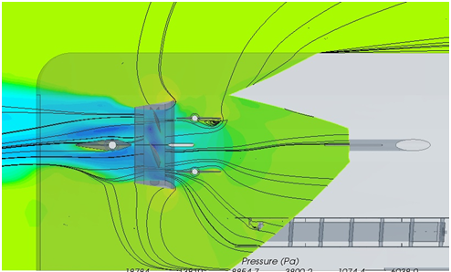
Even with the capabilities of “wake-adapted” computer design tools, there are instances where full 3D numerical analysis codes are essential. These codes are most widely represented by general-purpose CFD tools, there are numerous propeller-specific flow codes (used principally by propeller specialists) that would fall into this category.
The significant advantage made possible by these tools is to incorporate hull-propeller interaction into the process, which allows for observation of flow and a level of detail that previously would only be possible with extensive model testing. They can help a designer determine the full inflow wake field including the effect of appendages or to incorporate upstream vortex turbulence that might be shed into the propeller.
Contemporary blade-element and 3D codes offer the best outcomes when used together. They can mutually validate performance predictions, and can be coupled to take advantage of the hull-propeller interaction provided by 3D codes with the computational efficiency of wake-adapted blade-element tools. This is the state-of-the-art of “design for performance”, and is something that we could not imagine fifty years ago.
The future of propeller design
As we read the tea leaves and prognosticate what another five decades may bring, I reflect back on the early days of personal computers and how we greatly misunderstood the arc of their influence on our lives. It will be very interesting to see how new innovation in hardware and software affect how we design propellers and what is designed.
Ever-increasing computational speed means that we can achieve greater precision in in our design, which is definitely a good thing. Yet I wonder how much of the “art of design” will be lost as we place a larger burden on computer codes to conduct propeller design. Hydrodynamics is a messy business. Will we continue to know what design objectives are important? Can the computer juggle all of the design requirements that we as naval architects currently manage? Does it matter?
I think it does. But don’t take this as a complaint, a dire warning, or even a longing for “the good old days” (although I suspect I am periodically accused of the latter). Take this as a challenge to advance our understanding, education, and training in the discipline of propeller design in the context of new computational power, and to apply these tools for the best possible outcomes for our clients and customers. Just like we have for the last fifty years.
About HydroComp
Since 1984, HydroComp has been a leader in providing hydrodynamic software and services for resistance and propulsion prediction, propeller sizing and design, and forensic performance analysis. Through its unique array of software packages and services, HydroComp now serves over 1200 naval architectural design firms, shipyards, yacht owners, ship operators, propeller designers, universities and militaries around the globe.
For more information, contact: Jill Aaron, Managing Director
HydroComp, Inc.
15 Newmarket Road, Suite 2
Durham, NH 03824 USA
+1 603-868-3344
jill.aaron@hydrocompinc.com
www.hydrocompinc.com
Download the full article here: RINA: 50 Years of Propeller Design with Computers.pdf